 After I
finished building the observatory building and dome, for a
number of years I used my 12.5” Dall-Kirkham. However, the
RA and DEC drives, and telescope control software (none),
was completely inadequate to do serious astronomy. It was a
good telescope in its time, the mid 1970’s, but not now. In
an attempt to bring it up to modern standards I purchased a
Paramount. However, the positioning of the block pier in the
observatory was designed for a fork mount. I attempted to
make the Paramount German equatorial mount work by having
fabricated a heavy rectangular steel platform that jutted
out from the top of the block pier. I subsequently, after a
lot of work, that this was nutty. Luckily, I managed to find
a buyer in Australia for the Paramount. It had never been
used. Software-Bisque was very nice in transferring a new
Paramount warranty to the buyer. This all took place around
2004-2005. At this time, Jeff Hopkins, a renowned
photometrist, suggested I buy the Meade 16”. As it turned
out I had the money because I had just sold my Phoenix home
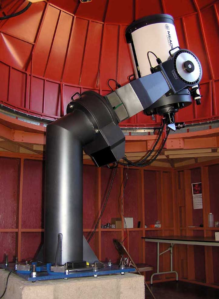
in 2004. I am partial to fork mounts and so I bought the 16”
Meade LX200R through Starizona. Starizona has been very good
to me over the years. The 16” saw first light on February
17th, 2006. I am very happy with it. The optics are very
good. The images through the eyepiece are just as good as
through my 12.5” Dall-Kirkham and that is optically a good
telescope. To date, the TCS appears like it will do
everything I want it to. I believe I have a good telescope,
contrary to its bad reputation, because I believe Scott
Roberts, who now owns Explore Scientific, at the time worked
for Meade and made sure I got a good scope. On the other
hand, maybe Meade years ago always made good telescopes,
with a very few exceptions that were sensationalized.
After I
finished building the observatory building and dome, for a
number of years I used my 12.5” Dall-Kirkham. However, the
RA and DEC drives, and telescope control software (none),
was completely inadequate to do serious astronomy. It was a
good telescope in its time, the mid 1970’s, but not now. In
an attempt to bring it up to modern standards I purchased a
Paramount. However, the positioning of the block pier in the
observatory was designed for a fork mount. I attempted to
make the Paramount German equatorial mount work by having
fabricated a heavy rectangular steel platform that jutted
out from the top of the block pier. I subsequently, after a
lot of work, that this was nutty. Luckily, I managed to find
a buyer in Australia for the Paramount. It had never been
used. Software-Bisque was very nice in transferring a new
Paramount warranty to the buyer. This all took place around
2004-2005. At this time, Jeff Hopkins, a renowned
photometrist, suggested I buy the Meade 16”. As it turned
out I had the money because I had just sold my Phoenix home
in 2004. I am partial to fork mounts and so I bought the 16”
Meade LX200R through Starizona. Starizona has been very good
to me over the years. The 16” saw first light on February
17th, 2006. I am very happy with it. The optics are very
good. The images through the eyepiece are just as good as
through my 12.5” Dall-Kirkham and that is optically a good
telescope. To date, the TCS appears like it will do
everything I want it to. I believe I have a good telescope,
contrary to its bad reputation, because I believe Scott
Roberts, who now owns Explore Scientific, at the time worked
for Meade and made sure I got a good scope. On the other
hand, maybe Meade years ago always made good telescopes,
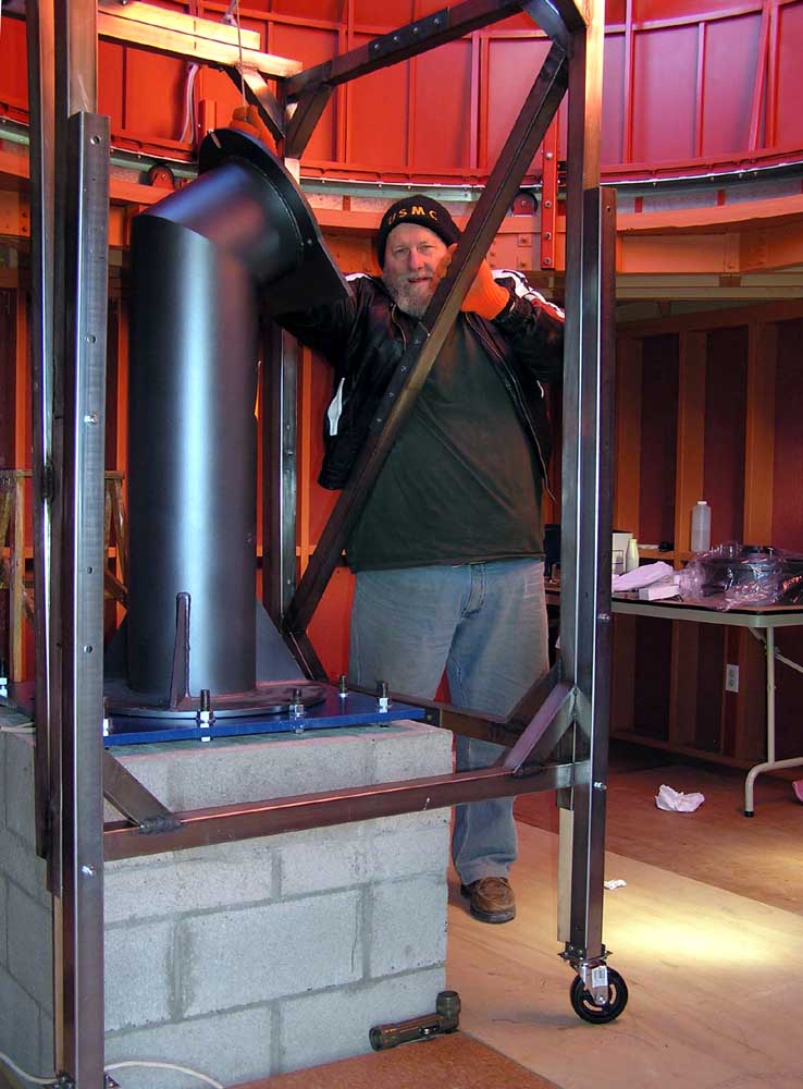
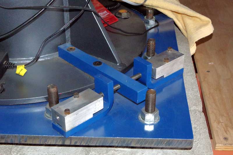
with a very few exceptions that were sensationalized. The permanent equatorial pier from Meade is very well built. The diameter of the pier is 10” and is made of ¼” thick steel. Top plate and bottom base are of ½” thick steel. Because my observatory already had a 32” square block pier I could not mount the Meade pier in the usual manner, the usual manner being bolting it to a concrete floor. Consequently, I had to come up with a different mounting method, which resulted in a much better method for polar aligning the telescope. The standard procedure for polar alignment is to apply brute force to move the pier in the azimuth direction and using shims where it bolts to a concrete floor for the altitude adjustment. This cannot be done on my block pier because the pier has a hollow central square hole formed by the six cinder blocks of the pier, and all the cinder block holes were grouted, each terminating with a ¾” J-bolt: there are twelve block holes and so there are twelve J-bolts at the top of the pier. The round base of Meade’s steel pier is 24” in diameter. To fit the Meade steel pier within the perimeter of these J-bolts, Meade turned down the diameter to 22.5”, at no extra charge.